
Reverse engineering is a structured engineering methodology used to convert physical components into accurate, validated digital models when original design data is unavailable, incomplete, or unreliable. In modern manufacturing and quality driven industries, reverse engineering is not limited to geometry reproduction; it focuses on recovering design intent, verifying functional integrity, and ensuring manufacturability. By integrating advanced measurement technologies, engineering judgment, and controlled validation steps, the reverse engineering process enables organizations to support design validation, failure analysis, supplier development, and product optimization with confidence. This document defines a standardized reverse engineering process to ensure consistency, accuracy, and engineering reliability across all projects.
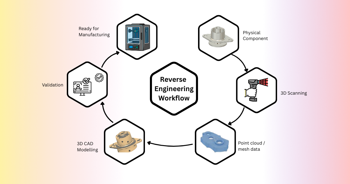
Data capture is the foundation of the entire reverse engineering process. The objective of this phase is to accurately digitize the physical component while respecting functional requirements, tolerances, and surface complexity.
The choice of measurement technology depends on several factors, including component size, material, complexity, required accuracy, and inspection objectives: 3D laser scanners are well suited for large components and free-form surfaces, offering fast data acquisition with good global accuracy. Structured light scanners provide high resolution surface detail and are commonly used for medium-sized components requiring tight tolerances. Coordinate measuring machines are used for precise inspection of prismatic features, datums, and critical functional dimensions. Industrial CT scanning enables full internal geometry capture, including hidden cavities, wall thickness variations, and internal defects.
Before 3D scanning begins, components must be cleaned, degreased, and sometimes coated with matte spray to eliminate reflectivity. Fixturing is planned to minimize occlusions, and multiple 3D scan orientations are defined to ensure complete coverage. Critical functional areas such as mating interfaces, bores, sealing surfaces, and load bearing features are prioritized.
The result of this phase is a raw point cloud or polygon mesh, representing the as-built geometry of the component. While highly detailed, this data is not yet suitable for 3D CAD or manufacturing and must undergo extensive refinement.
Raw 3D scan data is inherently imperfect. Environmental noise, reflective surfaces, 3D scan overlap errors, and shadowed regions can introduce inaccuracies. The data processing phase focuses on refining this raw input into a clean, reliable digital reference.
Noise Reduction and Outlier Removal: Noise filtering algorithms are applied to eliminate stray points and surface irregularities that do not represent true geometry. This step is critical when working with castings, forged parts, or worn components where surface texture can distort measurements.
Hole Filling and Surface Repair: Missing data caused by occlusions or line-of-sight limitations must be reconstructed logically. Holes are filled using curvature-based interpolation while ensuring that reconstructed surfaces align with surrounding geometry and functional intent.
3D Scan Alignment and Registration: When multiple 3D scans are captured, they must be accurately aligned into a single coordinate system. This is achieved using feature-based alignment, target-based alignment, or best fit algorithms. Proper alignment ensures that dimensional relationships across the component are preserved.
Mesh Optimization: The mesh is decimated where excessive density is unnecessary and refined where high detail geometry is required. The goal is to balance data accuracy with computational efficiency.
Output of the Data Processing Phase: The result is a clean, watertight, high fidelity mesh or point cloud that accurately represents the physical component and serves as a reference for 3D CAD reconstruction.
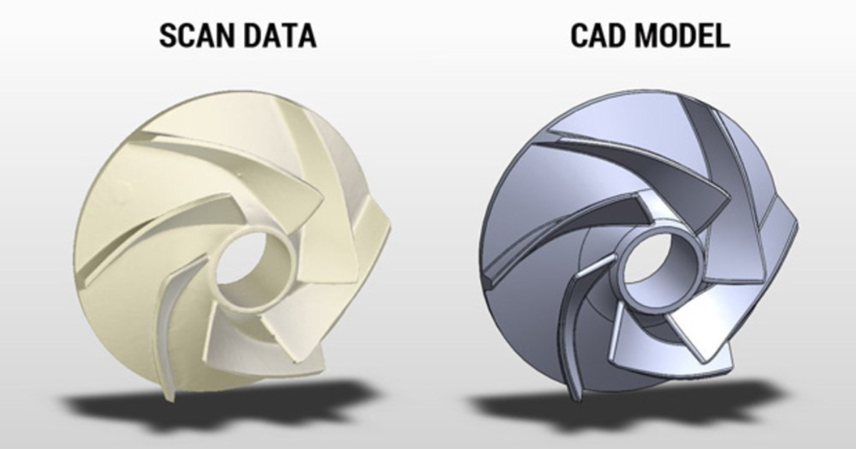
This phase is the most critical and value-driven step in reverse engineering. Instead of converting 3D scan data directly into a mesh based solid, designers reconstruct the part as a fully parametric, feature-based 3D CAD model. Mesh models are non-editable and unsuitable for manufacturing changes, tolerance control, or product lifecycle management. Parametric models, by contrast, allow dimensional control, feature suppression and modification, design optimization, easy reuse for variants and upgrades, and feature reconstruction strategy
Using the cleaned 3D scan as a reference, engineers recreate sketch-driven features such as extrusions, revolves, lofts, fillets, chamfers, and patterns. Cylindrical features are reconstructed using true axes, planes are re-established using functional datums, and symmetry is restored wherever applicable.
Design Intent Recovery: A key objective is to distinguish functional geometry from as-built deviations caused by manufacturing variation, wear, or deformation. Engineers apply best-fit logic and functional reasoning to recover nominal dimensions rather than blindly replicating scan noise.
3D CAD Tools Used: Industry standard 3D CAD platforms such as SolidWorks and Autodesk are commonly used due to their robust parametric modeling, surface reconstruction, and interoperability capabilities.
Output of the Parametric Modeling Phase: The deliverable is a fully editable, dimension-driven 3D CAD model that accurately represents the intended design and is suitable for manufacturing and engineering analysis.
Once the parametric model is complete, it is evaluated beyond geometry accuracy. This phase ensures the design is optimized for manufacturing feasibility, performance, and cost efficiency.
Material Analysis: Material analysis is performed to identify the component’s material composition, microstructure, and mechanical properties, which are critical for accurate replication, improvement, or failure analysis. Techniques such as spectroscopy (XRF, FTIR, OES) are used for chemical composition, microscopy (SEM, TEM) for microstructure evaluation, and hardness or tensile testing for mechanical strength assessment, ensuring correct material grade selection and manufacturability.
Design for Manufacturability (DFM): The 3D CAD model is reviewed and modified to meet manufacturing constraints. This includes adding or correcting draft angles for molding and casting, optimizing wall thickness to reduce sink marks and warpage, relieving sharp internal corners to minimize stress concentration and improve tool life, and redesigning undercuts or inaccessible features to suit machining and tooling limitations.
Tolerance Definition and GD&T: Functional tolerances are assigned to critical features based on performance and assembly requirements. Geometric Dimensioning and Tolerancing (GD&T) is applied to control form, orientation, location, and runout, ensuring repeatable manufacturing quality and reliable assembly performance.
Process-Specific Optimization: The design is optimized according to the selected manufacturing process. For additive manufacturing, part orientation and feature redesign reduce support structures; for CNC machining, tool accessibility and fixturing are validated; for casting, parting lines, gating systems, and shrinkage allowances are evaluated.
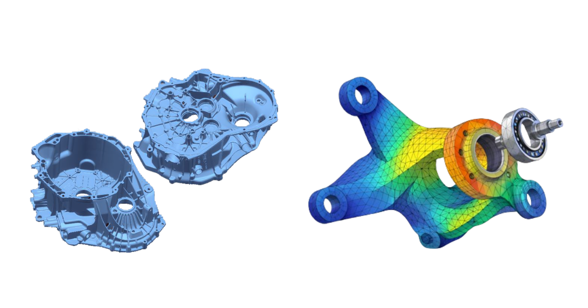
Engineering Analysis (When Required): Engineering simulations such as finite element analysis (FEA), thermal analysis, or fatigue analysis are conducted to validate structural integrity, stiffness, thermal behavior, and lifecycle performance under real operating conditions.
Output of the Optimization Phase: The final output is a manufacturing-ready, material-qualified 3D CAD model that balances functional performance, quality, cost efficiency, and scalability for production.
Validation is the final quality gate in the reverse engineering workflow. It ensures that the reconstructed 3D CAD model faithfully represents the physical component within defined acceptance criteria.
Functional Verification: Critical interfaces, assembly features, and performance-related geometries are reviewed to confirm that functional intent has been preserved or improved.
Documentation and Data Release: Once validated, the 3D CAD model is finalized and released in standard neutral formats such as STEP or IGES, ensuring compatibility with manufacturing partners, inspection systems, and PLM platforms.
Manufacturing: Pre-manufacturing readiness activities confirm manufacturing feasibility, finalize materials, define quality and inspection plans, and complete engineering approvals. Manufacturing execution then includes tooling and process development, trials, and controlled production with in process inspections. Finally, post-manufacturing, the 3D CAD model is digitally compared against the original 3D scan data. Color deviation maps highlight dimensional differences, enabling engineers to identify and correct any deviations beyond allowable tolerances. Validation through first article inspection, functional testing, and deviation analysis closes the loop, ensuring consistent quality, repeatability, and continuous improvement from reverse engineering to full scale production.
A disciplined reverse engineering process transforms physical components into reliable engineering knowledge rather than isolated digital replicas. By following a structured workflow, from requirement definition and measurement planning to design intent reconstruction, validation, and controlled release, organizations can achieve high confidence in reconstructed 3D CAD data and downstream engineering decisions. This standardized approach ensures dimensional accuracy, functional reliability, and manufacturability while enabling continuous improvement and knowledge retention. When executed as an engineering process rather than a software task, reverse engineering becomes a strategic capability that supports quality, innovation, and long term product sustainability.
RA Global Tech Solutions delivers advanced reverse engineering solutions to customers across India, Germany, USA, UK, Dubai, Canada, and Japan, supporting diverse industries including automotive, aerospace & defense, tooling, heavy industries, and industrial manufacturing. RA Global Tech Solutions specializes in end to end reverse engineering workflows encompassing high-accuracy 3D scanning, CT measuring based internal geometry reconstruction, 3D scan to 3D CAD modeling, deviation analysis, and design intent recovery. By combining advanced metrology technologies with strong engineering judgment and process driven validation, RA Global Tech Solutions enables customers worldwide to recover legacy data, validate supplier components, resolve field failures, and achieve manufacturable, design ready 3D CAD with confidence and consistency.
© 2026 RA Global Tech Solutions
Site design and developed by Rajkar Global