
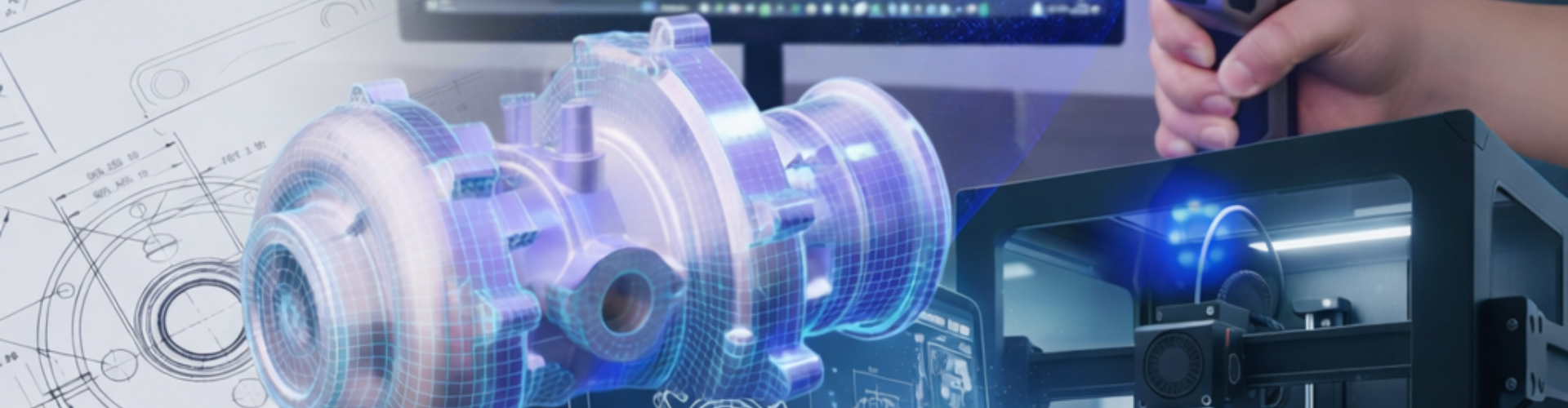
Using 3D scanning, reverse engineering, 3D CAD design, FEA analysis, and modern manufacturing, an existing part or old design can be quickly converted into an accurate, ready to produce component. This 3D scan to manufacture process helps industries replace parts faster, improve part strength and quality, and reduce material waste, making manufacturing more efficient and sustainable.
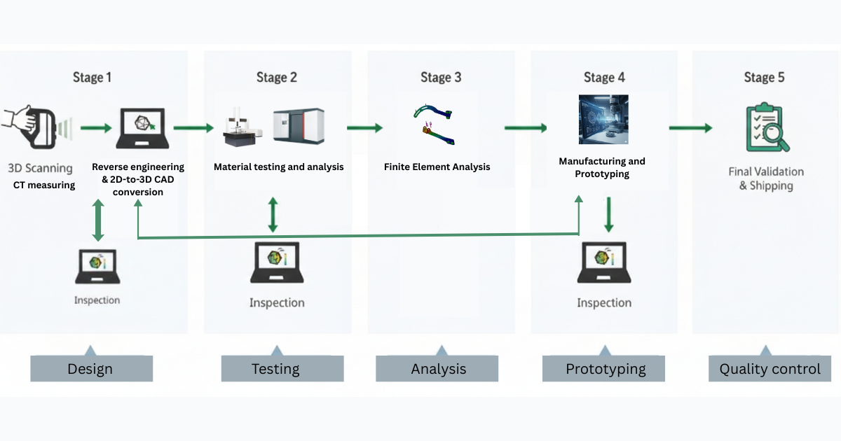
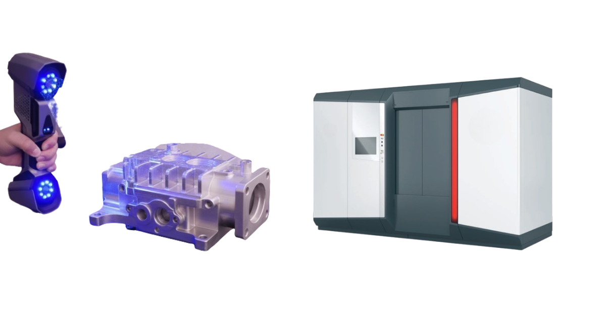
The process begins by capturing the physical part using advanced 3D scanning and CT measuring technologies. Optical 3D scanning is used to record the external geometry of the component in high detail, capturing complex shapes, contours, and fine features that are difficult or impossible to measure manually. For parts with internal features, such as internal channels, hidden cavities, variable wall thickness, or composite structures, industrial CT measuring is used. CT measuring provides a nondestructive view inside the component, revealing internal geometry and defects without cutting the part open. Together, these 3D scanning methods create a complete digital dataset that represents the part exactly as it exists in the real world.
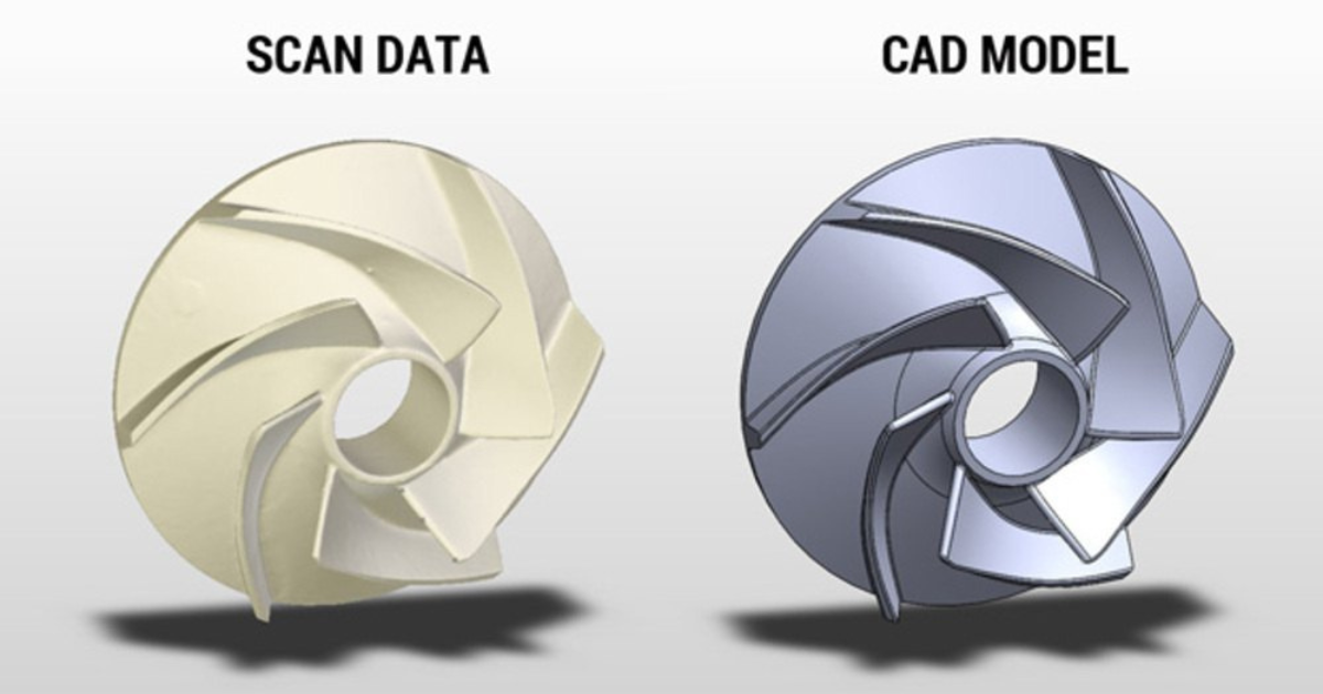
Once the 3D scan data is captured, the next critical step is reverse engineering. Raw 3D scan data, typically in the form of point clouds or mesh models, is not directly suitable for manufacturing or modification. Reverse engineering converts this 3D scan data into an intelligent, editable digital model that reflects the original design intent of the part. Designers analyze the geometry, identify functional features, and reconstruct the part as a clean, parametric 3D CAD model. This step allows worn or damaged areas to be corrected, missing features to be rebuilt, and tolerances to be redefined. Reverse engineering bridges the gap between physical reality and digital design, enabling accurate reproduction and improvement of existing components.
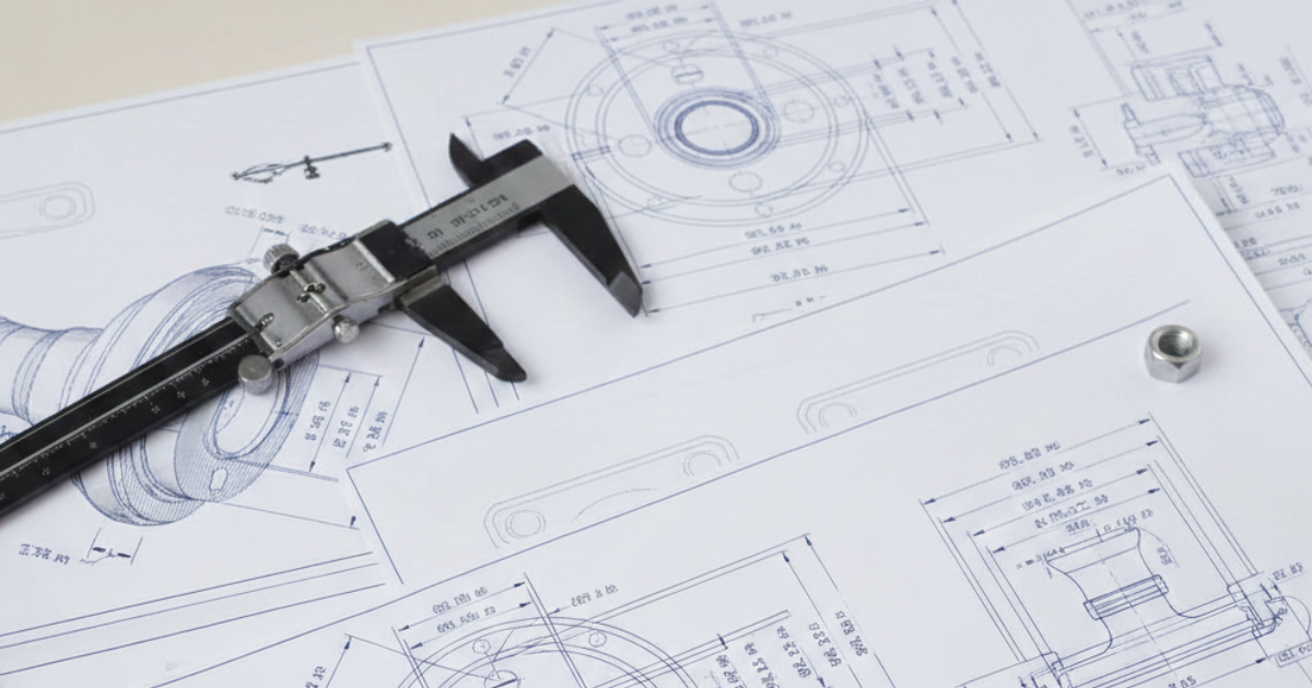
In many cases, clients may only have legacy 2D drawings or incomplete documentation rather than a physical part. In such situations, the process includes 2D-to-3D CAD conversion. Designers interpret 2D drawings, sketches, or PDFs and transform them into full 3D CAD models. This step involves understanding design intent, applying correct dimensions and tolerances, and creating a 3D dimensional representation that can be used for visualization, analysis, and manufacturing. Converting 2D data into 3D CAD not only modernizes legacy designs but also enables easier modification, simulation, and future scalability.
Whether derived from 3D scans or legacy 2D drawings, the finalized 3D CAD model serves as the central reference for the entire engineering workflow. At this stage, detailed dimensional, material, and composite analysis is carried out to understand how the component behaves structurally and under service conditions.
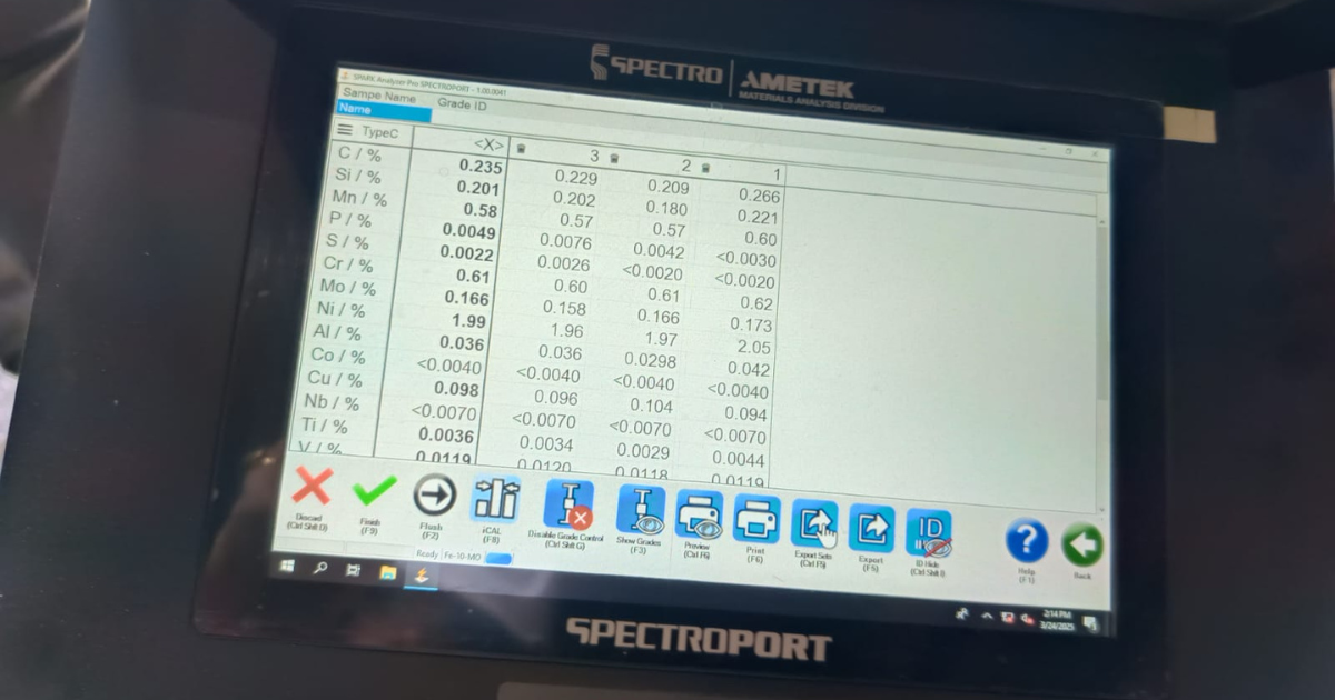
Spectrometer analysis is employed for accurate material identification and chemical composition verification. It confirms elemental composition, detects alloying elements, and ensures compliance with specified material grades, particularly critical when original material documentation is unavailable.
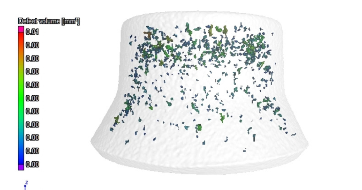
Computed tomography scan data is used to evaluate internal material consistency, identify voids, porosity, or inclusions, and analyze fiber orientation in composite components. This internal visibility provides valuable insight when validating assumptions or pursuing performance improvements.
In parallel, Coordinate Measuring Machine inspection verifies critical dimensions, geometrical tolerances, and form accuracy against the 3D CAD model. Together, CMM inspection, spectrometer analysis, and CT scanning provide comprehensive dimensional and material assurance, ensuring that redesigned or reproduced components meet required strength, durability, safety, and regulatory standards.
With a validated 3D CAD model in place, designers can focus on sustainability and design optimization. Digital engineering allows material usage to be reduced without compromising performance. Wall thicknesses can be optimized, unnecessary mass removed, and features refined to minimize waste during manufacturing. This approach reduces raw material consumption, lowers energy usage, and supports environmentally responsible production. Sustainability becomes a built-in advantage of the digital workflow rather than an added constraint.
Surface optimization is another key benefit of working with accurate 3D scans and 3D CAD data. Over time, physical parts experience wear, deformation, and surface degradation. By analyzing 3D scan data, engineers can identify these issues and restore or improve surface conditions digitally. Surface finish, contact areas, sealing surfaces, and transition radii can all be refined to reduce friction, minimize wear, and eliminate stress concentrations. These improvements enhance part performance, increase service life, and reduce the likelihood of premature failure.
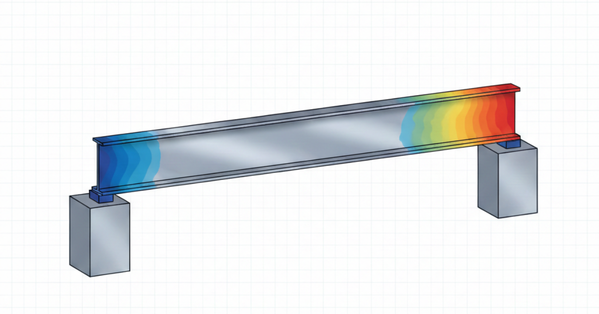
Before any physical production begins, the optimized 3D CAD model is subjected to finite element analysis. This virtual testing stage simulates real-world operating conditions such as mechanical loads, thermal effects, vibration, and fatigue. FEA helps designers identify stress hotspots, deformation zones, and potential failure points. By addressing these issues early in the digital phase, manufacturers avoid costly redesigns, repeated prototyping, and unexpected failures in the field. For clients, this means greater confidence that the final part will perform reliably in its intended application.
Once the design is validated, production prototyping begins. Depending on the application, the prototype may be manufactured using additive manufacturing, CNC machining, or hybrid methods. Prototyping allows physical validation of fit, assembly, and functionality within the actual operating environment. It provides an opportunity to confirm that the part integrates seamlessly with surrounding components and meets all functional expectations. Any final refinements can be incorporated before moving to full scale production.
After manufacturing, the part undergoes comprehensive inspection and validation. Dimensional inspection is performed using CMMs or 3D scanning systems to compare the manufactured component directly against the 3D CAD model. This ensures that all dimensions, tolerances, and geometric features meet design specifications. For critical components, CT measuring is again used to inspect the finished part for internal cracks, porosity, or defects that are not visible externally. This nondestructive inspection ensures both external accuracy and internal integrity.
The quality check phase consolidates all inspection and analysis data to confirm compliance with quality standards. Only parts that meet dimensional accuracy, structural integrity, and performance requirements are approved for use. Because the entire process is digitally documented from 3D scanning and reverse engineering to 3D CAD modeling and inspection, full traceability is maintained. This digital record enables repeat production, design updates, and future optimization with minimal effort.
The final step is dispatch. Approved parts are packaged and delivered, accompanied by the assurance that they have been engineered and manufactured using a robust, data-driven process. Digital 3D models and inspection data are retained for future reference, allowing rapid reproduction or scaling when needed.
The 3D scan to manufacturing process represents a fundamental shift in how parts and products are developed, replaced, and optimized. By digitally capturing existing components, converting them into intelligent 3D CAD models, validating performance through simulation, and ensuring quality through advanced inspection, manufacturers gain full control over accuracy, reliability, and repeatability. This approach eliminates uncertainty, reduces lead times, and enables continuous improvement whether the goal is part replacement, design enhancement, or production scalability. More than just a manufacturing method, this digital workflow creates long-term value by transforming physical parts into reusable digital assets, helping businesses operate more efficiently, sustainably, and confidently in an increasingly competitive world.
RA Global Tech Solutions is a leading engineering services provider specializing in 3D scanning, reverse engineering, 3D CAD design, and finite element analysis. The organization has a proven track record of delivering accurate, simulation-driven engineering solutions for complex components and assemblies. RA Global Tech Solution supports clients across heavy industry, automotive, electric vehicles, oil & gas, machinery, SPM, aerospace, and product engineering, enabling faster part replacement, design optimization, and performance validation. With a strong global presence and long-standing collaborations with customers in Muscat, the United Kingdom, Europe, Japan, and the UAE, RA Global Tech Solutions helps organizations transform physical components into reliable, production-ready digital assets.
© 2026 RA Global Tech Solutions
Site design and developed by Rajkar Global