
In modern manufacturing environments, validating existing components is just as critical as designing new ones. This is especially true for damper housing components, which often serve as load-bearing, alignment critical, and sealing interfaces in mechanical systems. When original 3D CAD data is unavailable, outdated, or unreliable, 3D scanning combined with 3D CAD reconstruction becomes a powerful tool for internal validation.
Dampers made up of metal alloys and rubber or polymers are used in various industries, which include automobile, railway, and heavy industries. Although they are often perceived as simple components, modern dampers are highly engineered assemblies, typically combining metal alloy housings with rubber or engineered polymer elements, and their performance depends heavily on internal geometry, material integrity, and precise interfaces. In today’s manufacturing environment, validating these components is just as critical as designing new ones, especially when original 3D CAD data is missing, outdated, or no longer representative of actual production parts.
This blog explains how the 3D scan to 3D CAD workflow is used to verify geometry, tolerances, and functional intent of a damper housing component, without disrupting production.
Damper housings frequently include complex internal cavities, non-uniform wall thicknesses, machined bores, and bonded elastomer interfaces. These features directly influence damping behavior, sealing integrity, fatigue life, and long term durability. Conventional inspection methods such as CMM measurement or external gauging can confirm visible dimensions, but they provide no insight into internal conditions. Critical issues, such as wall thinning due to casting core shift, over machining near pressure boundaries, internal porosity, or misalignment between metal and rubber elements, often remain hidden until functional failures occur. Destructive sectioning can expose some of these problems, but it damages valuable components and still offers only limited, localized information.
To overcome these limitations, manufacturers increasingly adopt a CT based 3D scan to 3D CAD workflow for damper validation. The process begins by defining functional inspection objectives, focusing on load paths, pressure critical regions, sealing zones, and metal elastomer interfaces. Using optimized X-ray parameters, the damper is CT scanned to capture both thick metal sections and fine internal details with high resolution. The resulting volumetric dataset represents the complete as manufactured condition of the component, internally and externally.
After scanning, the CT data is carefully processed to remove noise and imaging artifacts while preserving dimensional accuracy. Segmentation separates solid metal, elastomeric regions, internal cavities, and defects, creating a dataset suitable for detailed engineering analysis.
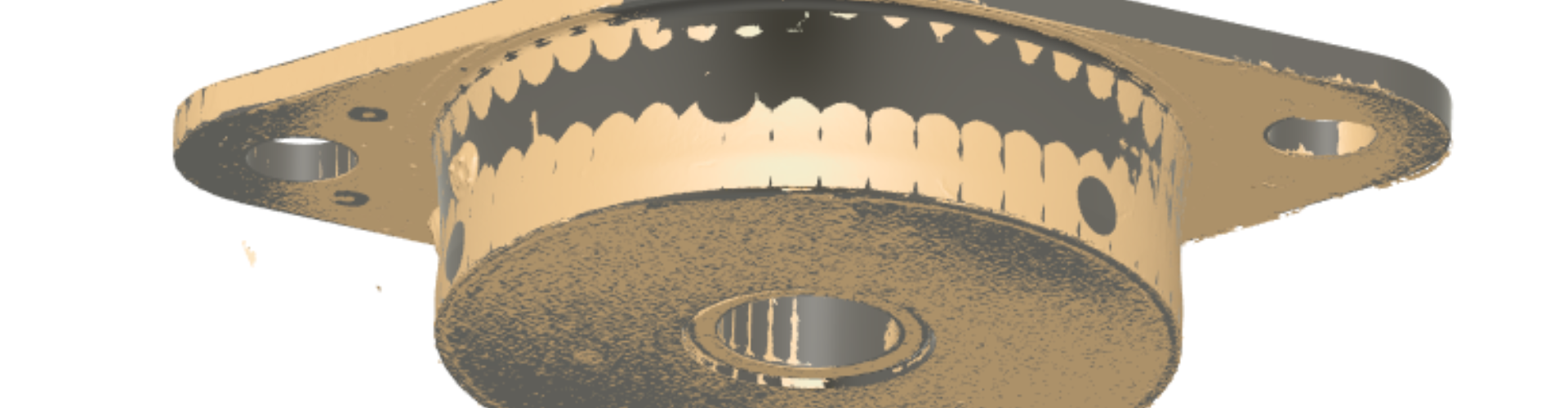
Digital cross sections are extracted at strategically important locations such as bore centerlines, mounting interfaces, sealing grooves, and transitions between cast and machined features. This analysis often reveals localized wall thinning near high stress regions, typically caused by casting variations or machining allowances exceeding design assumptions. In dampers, such thinning can significantly reduce fatigue life or compromise sealing performance under cyclic loading. CT analysis also helps distinguish between critical geometry-related risks and noncritical porosity, allowing corrective actions to be focused where they matter most.
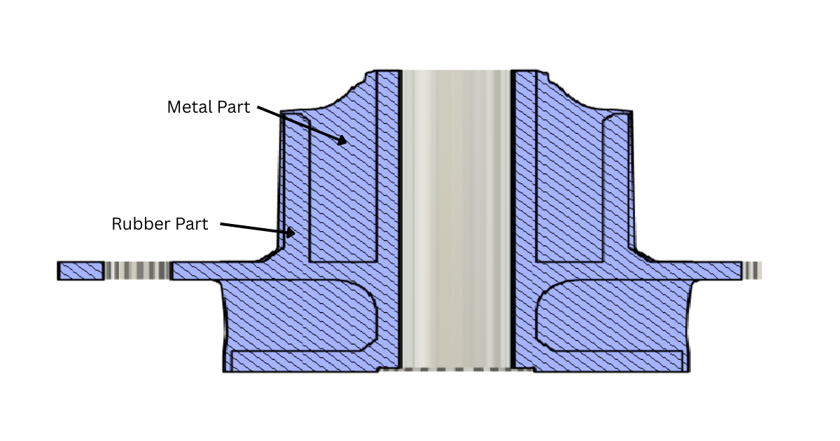
Many dampers rely on rubber or polymer elements for energy dissipation and sealing. CT scanning enables nondestructive evaluation of these interfaces, verifying correct positioning, bonding integrity, and material continuity between metal and elastomer components. This insight is especially important for dampers operating under pressure, temperature variation, or repeated dynamic loading, where even small interface deviations can lead to leakage, noise, or performance loss.
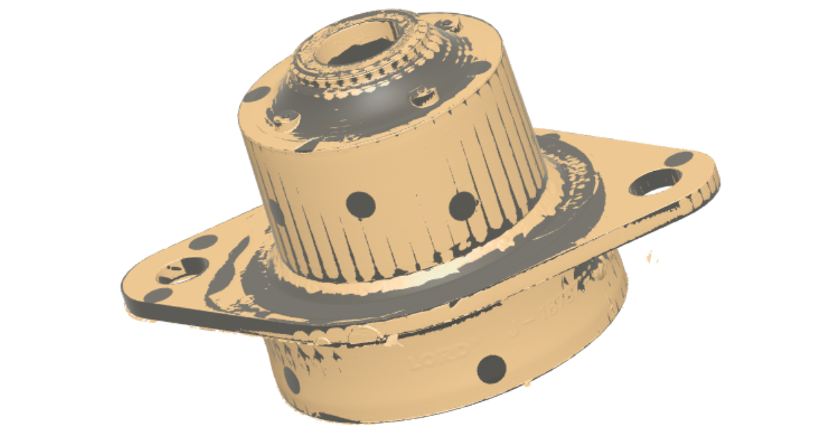
After completing the internal evaluation, the CT volume data was converted into accurate surface meshes capturing both external features and internal cavities. These meshes were optimized to preserve functional characteristics such as bore cylindricity, flange flatness, sealing faces, and critical transitions.
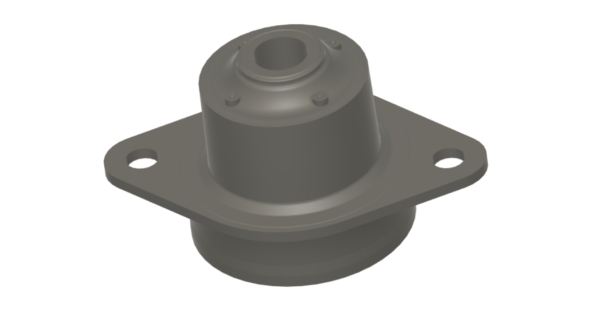
Using the extracted geometry, a fully parametric 3D CAD model was reconstructed. Functional engineering datums were re-established, and key features, including bores, planes, ribs, and transitions, were rebuilt using standard geometric definitions. Design intent was reintroduced by rationalizing nominal dimensions and enforcing symmetry where functionally required. The result was a clean, editable 3D CAD model suitable for simulation, redesign, and manufacturing validation.
The reconstructed 3D CAD model was validated against the original CT data through precise alignment and deviation analysis. Color deviation maps confirmed that all critical internal and external features were captured within acceptable tolerances. Particular attention was given to minimum wall thickness regions and sealing interfaces to ensure that the model accurately represented the areas responsible for field issues. This validation step provided the customer with confidence that the 3D CAD model reflected actual manufacturing conditions rather than theoretical or legacy design assumptions.
With a validated 3D scan to 3D CAD model in place, the customer was able to perform accurate structural and fatigue simulations using real internal geometry. Targeted design modifications were introduced to increase wall thickness in critical regions and adjust machining allowances, all without increasing overall component weight. Subsequent testing confirmed the elimination of leakage and demonstrated improved consistency across production batches.
By adopting a CT based 3D scan to 3D CAD approach, the customer avoided destructive testing, reduced redesign cycles, and significantly shortened development timelines. Most importantly, engineering decisions were driven by verified internal data rather than assumptions, substantially reducing the risk of future field failures.
Damper development starts with the selection of suitable metallic and elastomeric materials based on functional requirements such as load capacity, vibration frequency range, temperature exposure, and expected service life. Aluminum castings are commonly chosen for their lightweight and corrosion resistance, while SS 314 stainless steel castings are used where higher temperature capability and structural strength are required, forming the load-bearing housings and interfaces of the damper. Casting development then follows, covering mold design, gating and riser layout, and solidification control to achieve consistent wall thickness, dimensional accuracy, and internal soundness. Casting quality is verified through dimensional inspection and nondestructive evaluation to eliminate shrinkage, porosity, or internal defects that could affect damper performance.
In parallel, the rubber composite system is developed and tuned to achieve specified hardness, dynamic stiffness, and damping characteristics, along with required thermal, environmental, and fatigue resistance. A critical step is metal–rubber bonding, where surface preparation, primer and adhesive selection, and controlled molding parameters ensure repeatable and durable adhesion. Prototype dampers are then subjected to static stiffness, dynamic behavior, cyclic fatigue, and thermal aging tests, and the results are used to refine geometry, materials, and process parameters. This structured, process-driven approach ensures stable damper performance, long service life, and compliance with NVH, durability, and functional requirements.
This workflow demonstrates how CT based 3D scans to 3D CAD enable complete geometric transparency for complex cast components such as damper housings. By combining nondestructive internal inspection, detailed cross sectional analysis, and validated 3D CAD reconstruction, the customer transformed an uncertain physical component into a reliable digital foundation for engineering decision making. The result was improved performance, reduced risk, and a faster path to a robust and reliable final design.
We, RA Global Tech Solutions team, support automation industries worldwide with proven expertise in reverse engineering and the design, development, and validation of dampers and damper units for automotive and railway applications. From high-performance and luxury vehicles such as Ferrari and Mercedes-Benz to electric and mass market platforms including Tesla, Bajaj, and Tata Motors, our damper solutions enhance vehicle stability, reduce noise and vibration, and improve suspension durability, while in railway systems they support ride comfort, track stability, and fatigue life under cyclic loading. Our capabilities extend across vehicles and rail systems operating in key industrial and urban centers worldwide, including Coimbatore, Chennai, Pune, Paris, Toronto, Canada, Germany, Durham, Italy, and Dubai.
© 2026 RA Global Tech Solutions
Site design and developed by Rajkar Global