
In industrial pneumatic systems, tight tolerances are crucial for the smallest components, which are often complex in design and intricate in shape, as they play a vital role in ensuring the system's reliability, efficiency, and performance. The valve and nozzle require precise tolerances, and reengineering these parts demands advanced technology to accurately capture the profile of the fitting areas. Additionally, 3D printing these parts in the same material to ensure smooth functioning is a challenging task, but it is achievable with advanced 3D scanning and 3D printing technology. Components such as transparent housings, inserts, and protective caps are essential to air regulation, filtration, and flow control assemblies used across various manufacturing and automation environments. This blog explores how integrating 3D scanning, reverse engineering, CT measuring, and rapid prototyping was used to accurately capture, redesign, and validate such a component, enabling faster development and improved confidence before production.
Pneumatic system design demands strict control of tolerances to ensure functional performance, effective sealing, and energy efficiency, particularly because compressed air is highly compressible and inherently prone to leakage. This is especially critical for valves and nozzles, where small dimensional or geometric deviations can significantly affect airflow regulation, pressure stability, and response time. To manage manufacturing variability, tolerance definitions typically follow relevant ISO standards, addressing mechanical, pressure, and flow related requirements across components such as valves, nozzles, and seals.
Dimensional Tolerances (Fits): Precise dimensional fits between valve spools, sleeves, seats, and nozzle orifices are essential to prevent sticking, excessive friction, pressure loss, or uncontrolled air leakage. ISO 286-2 IT grades are commonly applied to maintain consistent functional clearances.
Geometric Tolerances (GD&T): Form and orientation tolerances such as cylindricity, circularity, concentricity, and axis straightness are critical for valve bores and nozzle passages. Deviations in these features can lead to uneven sealing, turbulent flow, and reduced valve efficiency.
Operating Pressure and Flow Control: Pneumatic valves and nozzles are typically designed to operate within a pressure range of 5.5–7 bar. Tight tolerances in regulating elements ensure stable flow control and predictable pressure drop while accounting for losses caused by internal restrictions, bends, and surface interactions.
Surface Roughness: Surface finish of valve spools, seats, and nozzle bores directly influences sealing performance, friction, and wear. Controlled roughness is essential to minimize leakage, reduce seal degradation, and maintain consistent airflow characteristics over the component’s service life.
Thermal Expansion Effects: Continuous airflow, pressure cycling, and friction can cause localized heating in valves and nozzles. Tolerance design must account for thermal expansion to prevent clearance reduction, sticking, or loss of sealing under operating conditions.
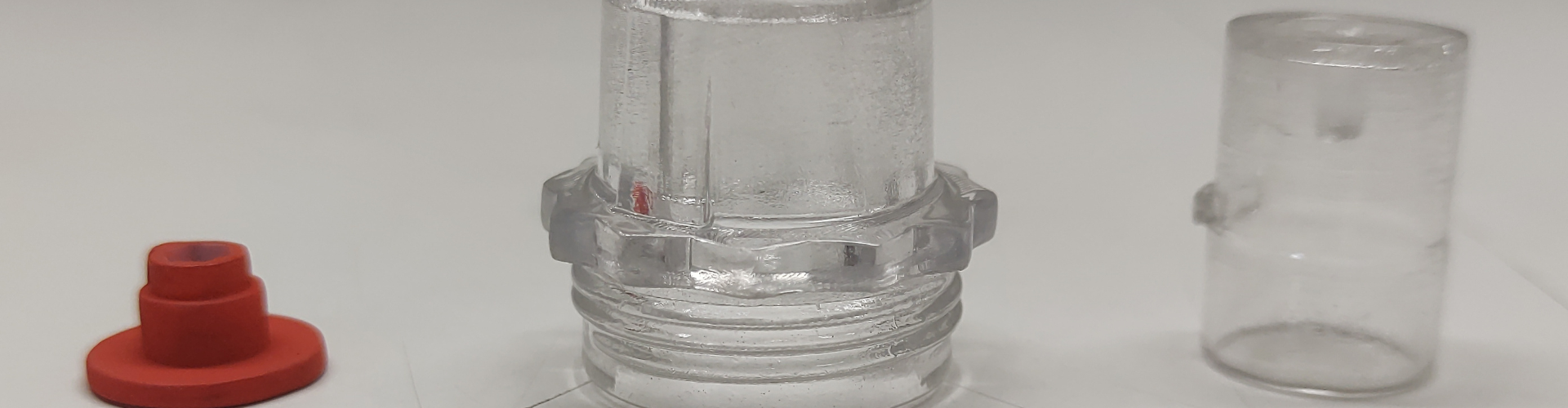
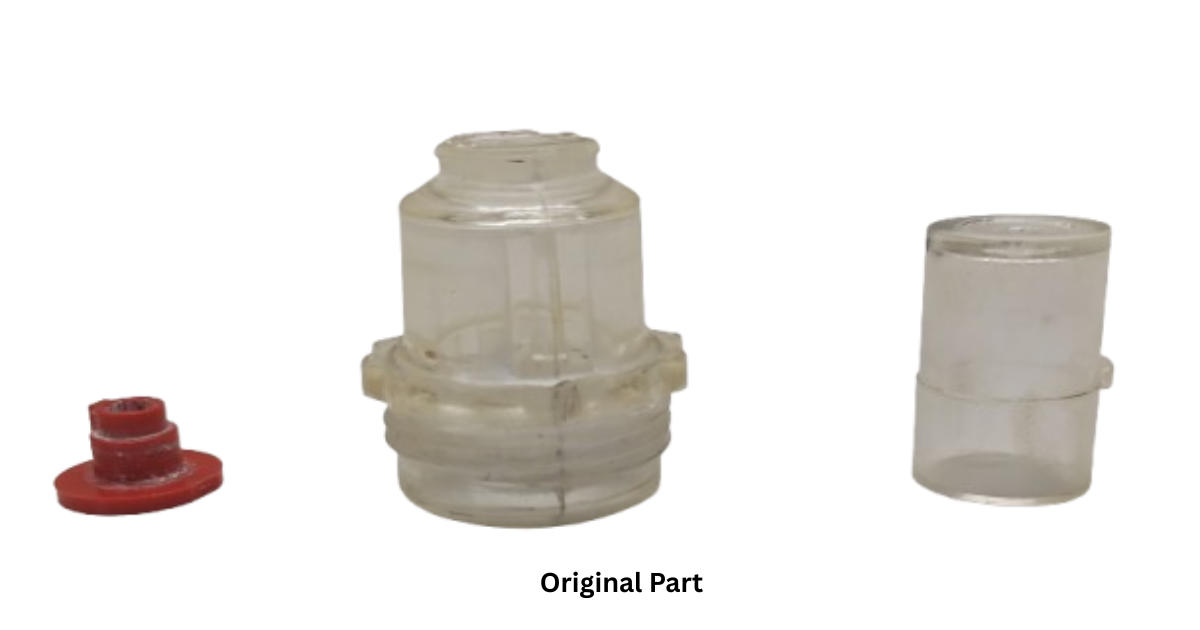
The component considered in this is a small multi part plastic assembly comprising a transparent threaded nozzle, a sealing or insert element, and a protective cap or sleeve. Components of this type are commonly used in pneumatic systems and industrial air processing applications, where dimensional accuracy, sealing integrity, and reliable assembly are critical to overall performance. Although relatively small in size, such parts perform essential functional roles within larger systems, making early stage design validation and fitment assessment crucial to ensure reliable operation under real world industrial conditions.
As the first step, 3D scanning was used to capture the as built geometry of the existing component, forming the basis for all subsequent engineering activities. A 3D laser or structured light 3D scanning system was employed to digitize the physical part, capturing millions of surface data points and generating a high resolution point cloud that accurately represented the component in its manufactured condition.
This approach was particularly important as the original 3D CAD data was unavailable and the component featured fine threads, grooves, and interlocking features that could not be reliably measured using conventional methods. By capturing the as manufactured geometry, the 3D scanning process accounted for real world variations such as molding deviations and dimensional inconsistencies, ensuring that the digital model reflected the actual part rather than nominal design assumptions.
A key challenge encountered during 3D scanning was the presence of transparent and reflective plastic surfaces, which caused light refraction and localized data noise, particularly around threaded and sealing regions. To address this, a temporary matte 3D scanning spray was applied, enabling consistent surface capture without altering the part geometry. This ensured complete and accurate 3D scan data, providing a reliable foundation for reverse engineering and downstream validation.
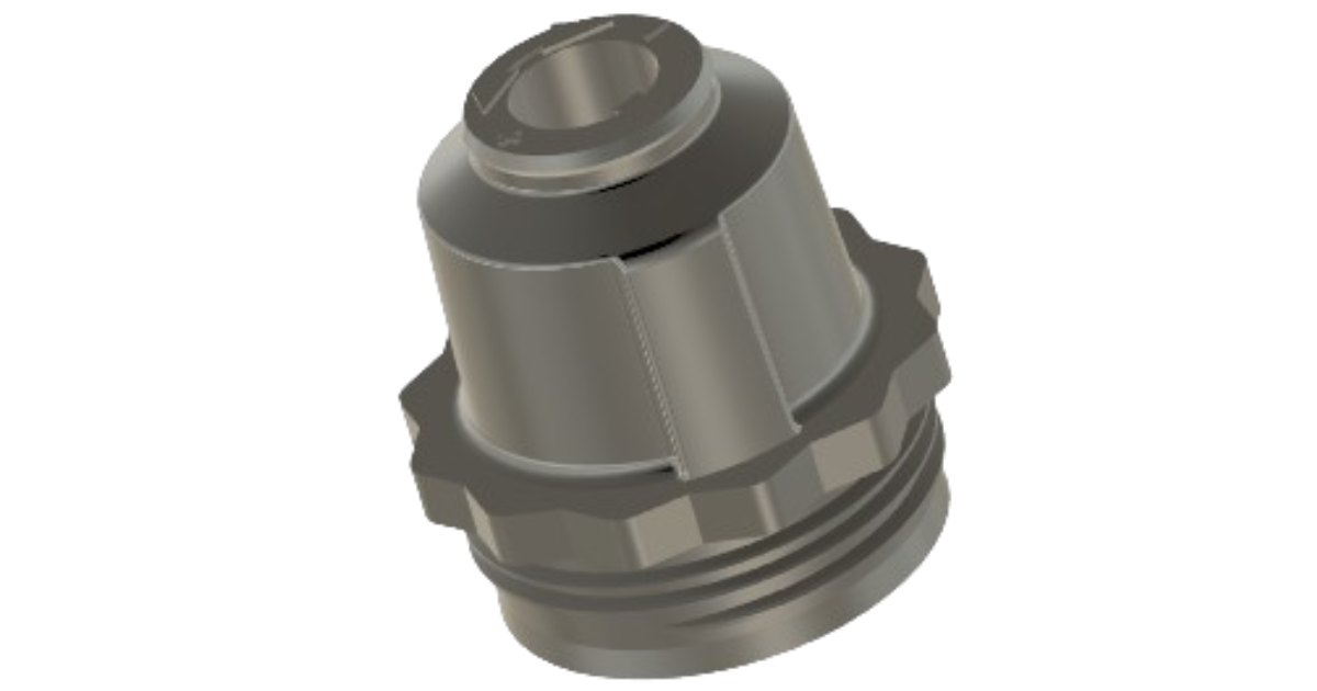
In the second stage, the 3D scanned mesh data was imported into reverse engineering and 3D CAD software to rebuild a clean, structured, and parametric 3D model of the component. This step focused on restoring the original design intent rather than simply replicating the 3D scanned geometry. Key activities included reconstructing cylindrical features and threads, defining critical sealing interfaces and mating surfaces, establishing functional tolerances for press fits and snap fits, and optimizing the geometry to improve fit, durability, and manufacturability. A major challenge at this stage was dealing with 3D scan noise, incomplete data in hidden regions, and deviations caused by molding or wear in the original part. If transferred directly, these imperfections could compromise functionality or lock defects into the new design. To address this, engineers selectively interpreted the 3D scan data, rebuilt critical features parametrically, and corrected inconsistencies, ensuring the final 3D CAD model was fully editable, dimensionally controlled, and suitable for prototyping and production.
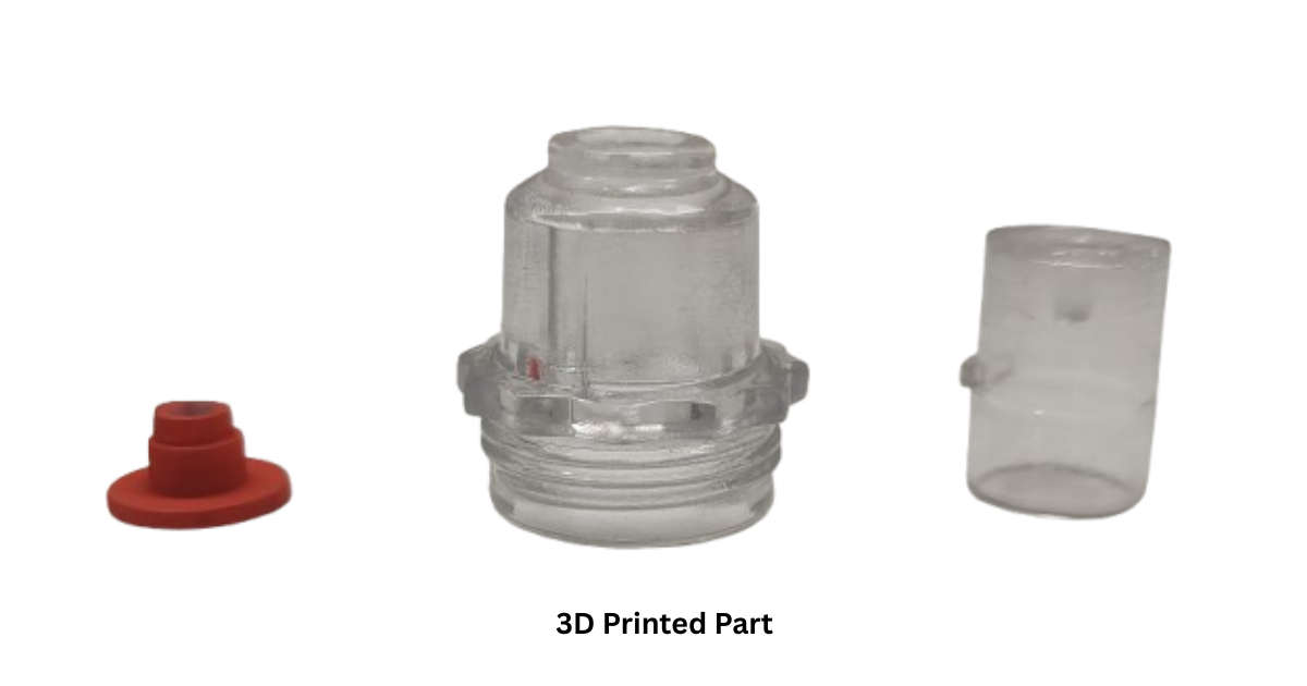
In the third stage, the finalized 3D CAD model was transferred directly to 3D printing to produce physical prototypes of the component. Rapid prototyping allowed engineers to verify fit and assembly between all mating parts, assess thread engagement and locking features, and evaluate handling, installation, and clearance under realistic conditions. This physical validation helped identify practical issues that are difficult to detect through digital simulation alone, such as assembly feel or minor interferences. By enabling real world testing without the need for costly tooling or long supplier lead times, rapid prototyping significantly accelerated the validation process and reduced development risk.
In the final stage, the 3D printed prototype was physically assembled and tested under functional operating conditions. During this phase, issues such as misalignment, air leakage, improper sealing, or excessive assembly force were identified through hands on evaluation. The findings from these tests were directly fed back into the 3D CAD model, enabling quick design adjustments. This closed loop workflow supported rapid design iteration, allowing revised models to be reprinted and retested within days rather than weeks, significantly accelerating development timelines while improving confidence in the final design before production.
The 3D scan to 3D CAD to rapid prototype process effectively bridges the gap between physical components and digital engineering. By capturing accurate as built geometry, restoring design intent in 3D CAD, validating performance through rapid prototyping, and addressing real world challenges early, engineers can develop reliable, production ready designs faster and with greater confidence.
With this 3D scan to 3D CAD to rapid prototype approach, RA Global Tech Solutions has successfully supported clients across the globe, delivering reliable reverse engineering and rapid validation solutions for industrial pneumatic and air processing components. By applying consistent engineering methodologies across diverse geographies and application requirements, RA Global Tech Solutions enables faster development, reduced risk, and a confident transition from legacy parts to production ready designs worldwide.
© 2026 RA Global Tech Solutions
Site design and developed by Rajkar Global