
3D CAD design for 3D printing is not just about shaping an idea; it requires understanding how materials behave, how various 3D printing technologies work, and how 3D CAD design choices affect the final outcome. Most 3D printing failures are not caused by the machine itself, but rather by the models, in which the 3D CAD designs are not done according to proper design guidelines.
Following are the most common 3D modeling mistakes 3D CAD designers make and how to fix them to ensure your 3D prints come out strong, functional, and flawless.
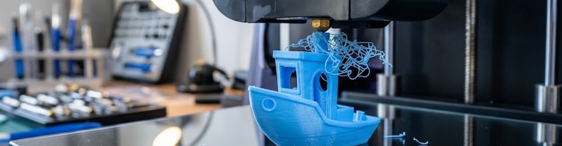
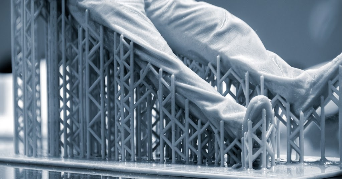
Support structures play a crucial role in 3D printing, especially for geometries involving overhangs and complex features.Minimizing support structures is key to improving print quality, reducing material usage, and saving post processing time. The goal is to design parts that are naturally self supporting wherever possible. While slicing software can automatically generate supports, relying entirely on software often results in poor surface finish, higher material consumption, and difficult post processing. In most 3D printing processes, overhangs beyond approximately 45° require support. If not properly planned, unsupported regions can sag, deform, or fail during 3D printing.
Instead of treating supports as an afterthought, they should be considered during the 3D CAD design stage itself. Smart 3D CAD design strategies can significantly reduce or even eliminate the need for supports. For example, replacing sharp horizontal edges with chamfers, designing self supporting angles, optimizing part orientation early, or splitting complex geometries into multiple components can improve 3D printability. 3D CAD designing with support structures in mind not only enhances 3D print quality but also reduces time, cost, and post processing effort.
One of the most common mistakes in 3D CAD design is assuming that all materials behave the same. In reality, every 3D printing material has unique mechanical, thermal, and structural properties. Some materials are strong and rigid, others are flexible or brittle, and each responds differently to stress, temperature, and 3D printing conditions. Because of this, a one size fits all 3D CAD design approach simply does not work.
The correct approach is to select the material at the very beginning of the 3D CAD design process, not at the end. Material choice directly influences how the part should be 3D CAD designed, including wall thickness, geometry, support requirements, and overall performance.
For different applications, the material should be chosen based on functional needs:
In addition to selection, material quality is equally important. High quality filaments from reputable manufacturers provide better consistency, improved layer adhesion, and more reliable mechanical performance.
Once the material is selected, the design must be adapted accordingly. Each material comes with its own design constraints and guidelines, such as minimum wall thickness, allowable overhang angles, load bearing capacity, and post processing requirements.
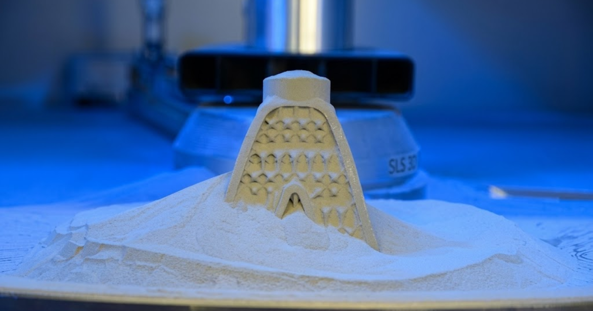
Porosity is a common issue in metal 3D printing, where tiny holes or cavities form within a part during the manufacturing process. These microscopic pores reduce the overall density of the component and can significantly weaken its mechanical properties, making it more susceptible to cracks or failure, especially under high stress or load conditions. This problem typically arises from two main sources. First, the quality of the metal powder itself can introduce porosity; for instance, certain powder production methods like gas atomization may lead to internal voids. However, the more frequent cause lies in the printing process. If the laser or energy input is too low, the metal does not fully melt, leaving gaps behind. On the other hand, excessive energy can cause molten material to splatter, also resulting in pore formation.
To minimize porosity and improve part performance, several strategies can be adopted. Using high quality raw materials from reliable suppliers is essential. Optimizing printing parameters such as laser power and scan speed helps ensure proper melting and fusion. Post processing techniques also play a crucial role; methods like hot isostatic pressing can eliminate internal voids and enhance mechanical strength. Additionally, for powder bed fusion parts, infiltration can be used to fill remaining pores, further improving density and durability.
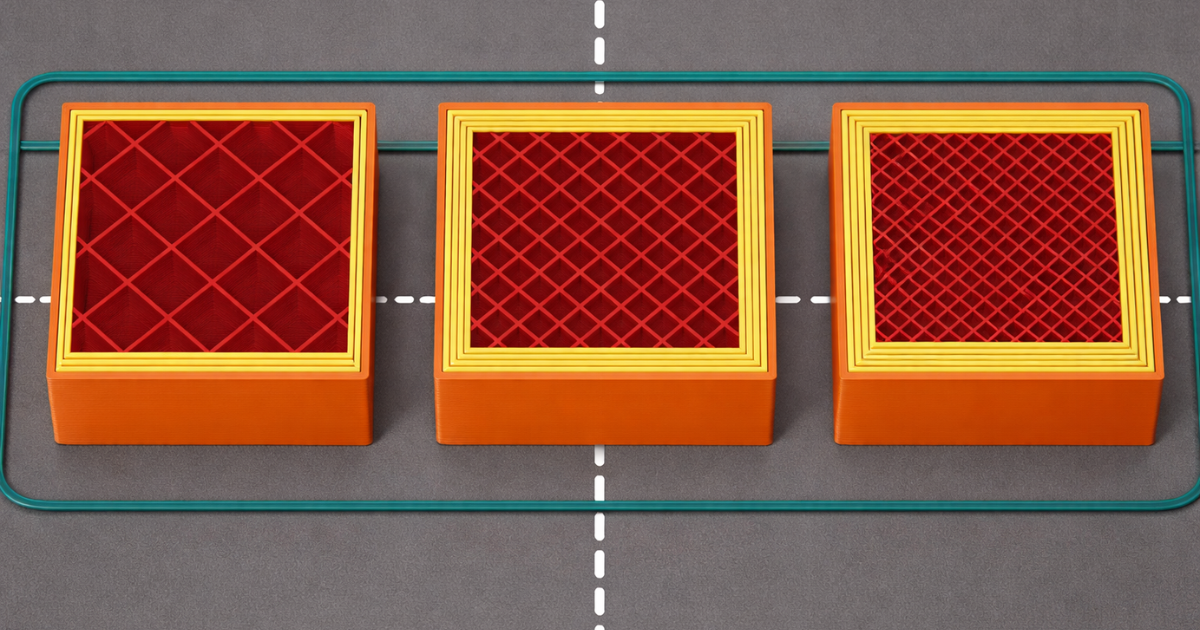
Wall thickness is a critical factor in 3D CAD design that directly impacts the strength, 3D printability, and overall efficiency of a part. 3D CAD designing walls that are too thin can result in fragile components or even complete 3D print failure, while excessively thick walls lead to unnecessary material usage, longer print times, and the possibility of internal stresses. Since 3D printing builds parts layer by layer using fixed process parameters such as nozzle diameter, wall thickness must be 3D CAD designed in alignment with these constraints. If not, the 3D printer may skip fine features, produce weak sections, or create dimensional inaccuracies.
Poor wall thickness 3D CAD design can lead to several common issues. Walls that are too thin may not 3D print properly or may break easily under minimal load. On the other hand, overly thick walls increase both cost and production time without proportional benefits. Inconsistent wall thickness across the part can cause uneven cooling, leading to warping or distortion, while thin unsupported features are more likely to deform during the 3D printing process.
As a general guideline for FDM printing, a minimum wall thickness of around 1 to 1.2 mm is recommended. Functional parts typically require wall thickness in the range of 1.5 to 3 mm, while load bearing components may need 3 mm or more depending on the application. For optimal results, wall thickness should be designed as multiples of the nozzle diameter; for example, with a 0.4 mm nozzle, using values such as 0.8 mm, 1.2 mm, or 1.6 mm ensures better print accuracy, strength, and consistency.
One of the most critical yet often overlooked aspects of 3D printing is layer orientation. Unlike traditional manufacturing methods, 3D printed parts are anisotropic, meaning their strength varies depending on direction. Parts are generally stronger within layers and weaker between layers. This makes orientation a key factor in determining mechanical performance. If a part is oriented incorrectly, it may fail under load due to poor layer adhesion, even if the design itself is correct.
For example, a hook 3D printed vertically may break easily because the load acts across layer lines, whereas printing it horizontally aligns the layers with the load, significantly improving strength. To optimize performance, parts should be oriented so that primary loads act parallel to the layers. 3D CAD designers should also avoid placing stress across layer boundaries and balance orientation with support requirements and surface finish considerations. A simple change in orientation can significantly enhance strength, durability, and 3D print success.
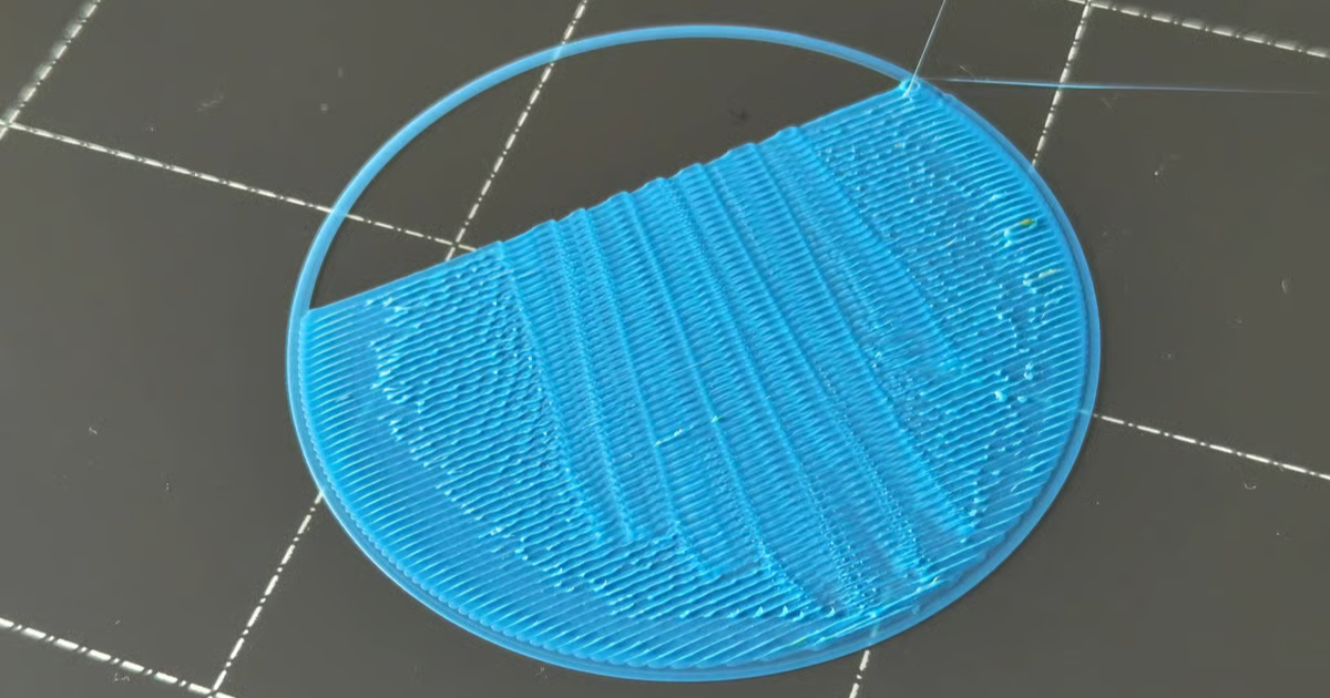
Curling edges and rough corners are common issues when 3D printing with high temperature filaments, primarily caused by inadequate cooling of the 3D printed layers. When the material remains soft for too long inside a heated chamber, it becomes prone to deformation, leading to lifted edges and uneven surface finishes. This problem can also arise from poor bed adhesion, where the part does not firmly stick to the build platform, creating internal stresses between layers that result in warping and curling.
To minimize these issues, it is important to improve layer cooling by adjusting the 3D printing environment. Lowering the chamber temperature or slightly reducing the extrusion temperature can help the material solidify faster and retain its intended shape. If curling appears at the beginning of the 3D print, it may indicate problems with the first layer, such as an unlevel build platform or excessive print speed. Ensuring proper bed leveling, optimizing first layer settings, and improving adhesion can significantly reduce deformation and lead to cleaner, more accurate 3D prints.
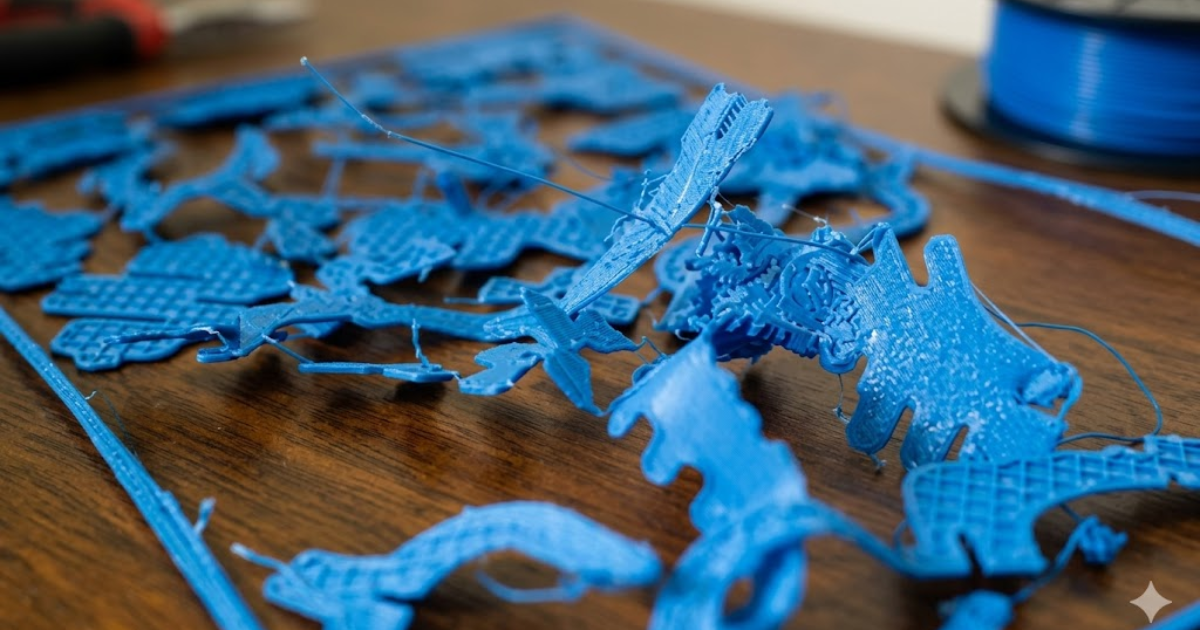
Sharp edges and delicate joints may look clean in your 3D CAD model, but in the real world 3D printing, they often become stress points that crack, warp, or fail under even light use. Thin connectors can snap during 3D printing or handling, and sharp 90° corners tend to concentrate stress, making your part far less durable than intended.
A softer, more forgiving approach is to gently round out your geometry. Adding fillets helps distribute stress more evenly, while chamfers can make edges 3D print cleaner and reduce the risk of curling. If certain areas of your 3D CAD design feel fragile, reinforcing them with ribs, gussets, or slightly thicker attachment points can dramatically improve overall strength without affecting the 3D CAD design is aesthetics. Replacing harsh internal corners with smooth curves also goes a long way in improving part longevity. And for parts that will bear weight or handle movement, running a quick stress simulation can help you refine the geometry before 3D printing.
By smoothing out edges and strengthening joints during the 3D CAD design stage, you create models that are not only easier to 3D print but also far more reliable once they are in use.
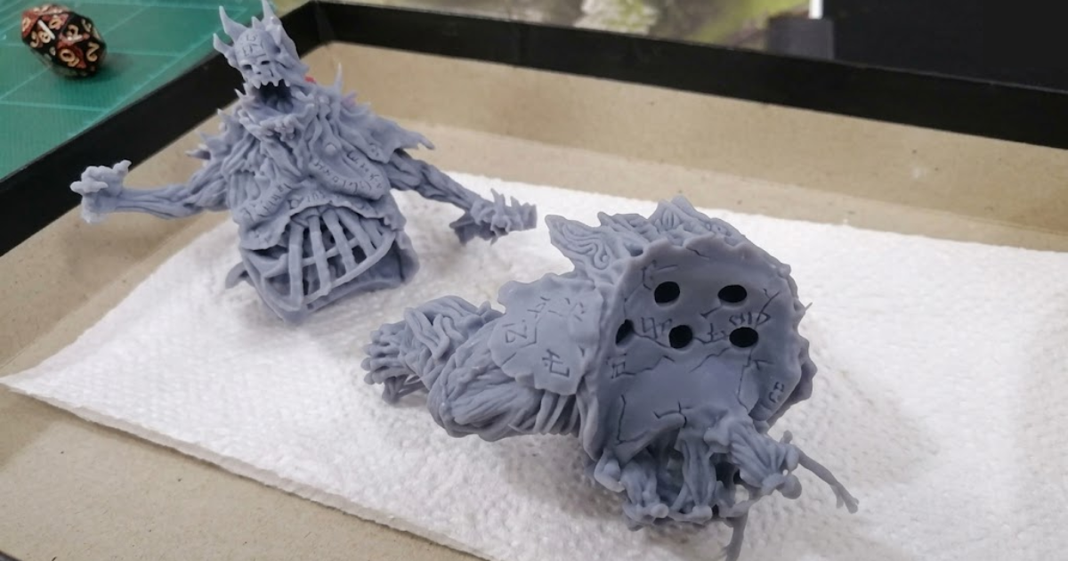
When hollowing out resin models in SLA 3D printing, failing to include at least two properly placed drainage holes is a critical 3D CAD design mistake. Without these openings, uncured resin becomes trapped inside the part, leading to increased weight, difficult cleaning, and incomplete curing. Over time, this trapped resin can create internal pressure buildup, which may cause cracks, deformation, or even sudden failure of the part. Incorporating adequate drainage holes ensures effective resin removal, reduces internal stress, and significantly improves the overall durability and reliability of the printed model.
|
|
Supported walls |
Unsupported walls |
Support and overhangs |
Embossed & engraved details |
Horizontal bridges |
Holes |
Connecting/moving parts |
Escape holes |
Minimum features |
Pin diameter |
Tolerance |
|---|---|---|---|---|---|---|---|---|---|---|---|
|
Fused Deposition Modeling |
0.8mm |
0.8mm |
45° |
0.6 mm wide & 2 mm high |
10 mm |
⌀2mm |
0.5 mm |
- |
2 mm |
3 mm |
±0.5%(lower limit ±0.5 mm) |
|
Selective Laser Sintering |
0.7 mm |
- |
- |
1 mm wide & high |
- |
⌀1.5 mm |
0.3 mm for moving parts & 0.1 mm for connections |
5 mm |
0.8 mm |
0.8 mm |
±0.3%(lower limit ±0.3 mm) |
|
Stereolithography |
0.5 mm |
1 mm |
Support always required |
0.4 mm wide & high |
|
⌀0.5 mm |
0.5 mm |
4 mm |
0.2 mm |
0.5 mm |
±0.5%(lower limit ±0.15 mm) |
|
Direct Metal Laser Sintering |
0.4 mm |
0.5 mm |
support always required |
0.1 mm wide & high |
2 mm |
⌀1.5 mm |
- |
5 mm |
0.6 mm |
1 mm |
±0.1 mm |
|
Binder jetting |
2 mm |
3 mm |
- |
0.5 mm wide & high |
|
⌀1.5 mm |
- |
5 mm |
2 mm |
2mm |
±0.2 mm for metal & ±0.3 mm for sand |
|
Material jetting |
1 mm |
1mm |
support always required |
0.5 mm wide & high |
|
⌀0.5 mm |
0.2 mm |
- |
0.5 mm |
0.5 mm |
±0.1 mm Conclusion |
3D CAD Designing a 3D model for 3D printing may seem overwhelming at first, but with a little patience and awareness, it becomes a smooth and enjoyable process. The key is to understand the material you are working with, stay mindful of the 3D printing technology you will use, and make thoughtful 3D CAD design decisions from wall thickness and tolerances to file resolution and geometry. As you practice, you will naturally start recognizing what works and what needs adjustment. And if you ever feel stuck, remember that there’s a world of tutorials, guides, and communities ready to help you learn and grow.
RA Global Tech Solutions is a leading engineering solutions provider specializing in advanced 3D printing and rapid prototyping services. Based in Mumbai, we deliver high precision, innovative manufacturing solutions to industries ranging from automotive and aerospace to healthcare and consumer products. At the core of RA Global Tech Solutions is capabilities is its expertise in transforming digital 3D CAD designs into functional physical parts using cutting edge 3D printing technologies. By building components layer by layer, the company enables the creation of complex geometries, customized 3D CAD designs, and high performance parts that are difficult or impossible to achieve through traditional manufacturing methods.
© 2026 RA Global Tech Solutions
Site design and developed by Rajkar Global